T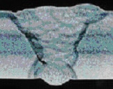 HE RELATIONSHIP BETWEEN MIG WELD MASS & WELD ENERGY. Most weld personnel are not aware that both GMAW (MIG), and also the Rutile EXOT-1, Gas Shielded Flux Cored weld processes have weld metal transfer and arc energy / plasma characteristics in which since the inception of these weld processes, have produced a poor relationship between the weld mass delivered, the weld speeds that result and the amount of weld / part energy generated.
 MIG WELD DEFECTS THAT CAN BE GENERATED BY THE WELD PROCESS RATHER THAN BY THE WELDER. When a weld shop uses Pulsed MIG or Spray Transfer on steels and alloys > 1/4, (> 6 mm), they typically should see superior fillet or groove weld fusion from the MIG spray mode and that applies to all metals. However MIG spray is too hot for vertical up welds and should likely noThe common weld defects that can be influenced by the weld process are;
- Lack off or inconsistent weld fusion. (enhanced with steels over 1/4 (>6mm) and with all sluggish alloys.
- Unacceptable weld porosity or trapped small slag.
- Cold weld starts, or weld end craters that may have micro weld shrinkage cracks.
MIG POLARITY INFLUENCE ON DISTORTION, CRACKS AND THE WELD QUALITY & PART PROPERTIES: With the Reverse Polarity, Electrode Positive Spray and Pulsed MIG weld transfer modes, you have the majority of the MIG plasma heat located in the upper portion of the MIG plasma in close proximity to the continuous fed weld wire tip. This RP localized energy in the upper portion of the MIG plasma creates a plasma heat concentration that results in the typical large weld Heat Affected Zones, and this heat affect also results with the much colder, arc on – arc off MIG short circuit weld mode.
MIG WELD ENERGY GENERATED AND WELD FUSION ATTAINED: In many instances you will find with MIG fillet welds, that the weld fusion attained on parts > 6 mm was marginal especially in the side walls. When MIG Spray and Pulsed MIG lack of weld fusion defects on the metals > 6 mm are often influenced by the high weld deposition rates that in contrast to SMAW and TIG, result in much faster weld travel rates attained with welds that lack sufficient energy / fluidity and time required to provide the weld fusion required. The lack of fusion may be further exasperated with rapid weave actions as in groove welds, or as the metal thickness increases, and when welding sluggish alloys like stainless, duplex and inconel.
Weld deposition rates have always had have a negative influence on Vertical up and Over head manual Pulsed MIG and also Gas Shielded Flux Cored welds on metals > 6 mm. These two manual, semi-automated weld processes will often require fast movement of the MIG gun which influences both the required manual welder skills and the weld fusion attained.
IF WELD PERSONNEL WOULD USE STRINGERS INSTEAD OF WEAVES THERE WOULD BE EXTENSIVE IMPROVEMENT IN ALL MULTI-PASS WELDS.
 MIG WELD STARTS – STOPS, WELD FUSION – CRATERS – CRACKS. Much of the “manual” MIG welding equipment” available in 2020, 70 plus years after it’s development, lacks the electronic ability to optimize weld both weld start – stops, these are areas in which weld defects will be common. In contrast, the additional controls in a robot enable these important features.
PULSED MIG PEAK TO BACKGROUND CURRENT INFLUENCE ON WELD FUSION: First I want to point out that if you want to attain the best possible MIG weld fusion, use a CV MIG power source and an 80 -20CO2 gas mix and set the weld in the Spray mode. When you use Pulsed MIG remember that the MIG plasma / weld energy is also influenced the Peak to the LOW Background weld current fluctuations which do little to enhance weld fusion.
Remember with gauge welds and aluminum welds less than 5 mm, the weld shop benefits from the lower open arc, lower energy pulsed MIG modes. With thicker metals or sluggish alloys you goal is to attain the best possible weld fusion.
As many have found out when manual Pulsed MIG welding code applications in which the wall thickness > 6 mm, in which the internal weld quality is verified WITH X-rays or Ultrasonic NDT , the pulsed MIG weld energy produced will often be insufficient for the weld mass produced and weld travel rates being utilized.
MIG & REACTIVE GAS MIXES INFLUENCE ON POROSITY – SLAG ISLANDS: As for weld porosity and small slag entrapment in the MIG welds, apart from the weld mass and weld freeze rates which influences these defects, the weld shop also has to remember that reactive MIG gas mixes that contain CO2 and Oxygen also influence the formation of these defects, as does the use of the common E70S- 6 MIG wires with argon mixes (too much silicon and manganese. As I have been trying to tell the apathetic automotive managers for close to 40 years, when using argon mixes use an E70S-3 wire, and you will see a reduction in slag on those robot welded surfaces. By the way I know a little about MIG gas mixes as I was a key writer of the US. AWS MIG Gas Specifications.
A sad Lincoln Power Wave, Automated Robot Crater Control on a Pulsed MIG Aluminum part.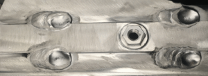
AS YOU CONTINUE TO REVIEW THE REVERSE POLARITY (RP) PULSED MIG AND FLUX CORED PROCESS, YOU WILL NOTE THAT THESE TWO PROCESSES SIMPLY CANNOT COMPETE WITH THE TIP TIG ARC PLASMA WELD TEMPERATURE WITH IT’S INERT PLASMA AND ELECTRODE NEGATIVE POLARITY.
No matter how sophisticated a weld shop’s RP Pulsed MIG power source is today, or will be tomorrow, to create the pulsed MIG weld drops, the weld shop is first using an arc weld process that provides approx. 50% of the arc energy generated by a TIP TIG weld, and also that pulsed MIG welds will spend 50% of it’s arc time time in a reactive plasma at a low back ground weld current typically between 80 – 120 amps.
For thirty plus years, I have been writing about the never ending lack of weld fusion Achilles Heel of all position Pulsed MIG welds on steels and alloy steels > 1/4 . And no matter what electronics are added to the Pulsed MIG power source, the reality has been with the pulsed background current characteristic there will often be “inadequate weld energy delivered to the weld mass (deposition) provided that drives the weld speeds used”. I also wrote numerous pages on this subject at my weldreality.com web site, and also in my training resources and in my “Management Engineer Guide to MIG” book.
MIG STT Left – MIG RMD right. Both attaining acceptable 5G root, vert down weld results.
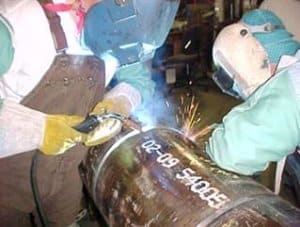
Above: Ed/ Em Training Exxon / Imperial Oil pipe welders on the different MIG weld transfer modes available to make 5G MIG welds on Nat Gas Pipe. For rotated open root pipe joints, MIG short circuit will produce welds on par with the STT, RMD or any Low pulsed MIG process.
Pipe weld shops need to be aware that when they use MIG Short Circuit for rotated pipe root welds, or use RMD or MIG STT or any other low pulsed modes, with the 5G position pipe root welds, in contrast to TIP TIG, they are using inferior arc weld processes that are not only sensitive to wire stick variations but also sensitive to root weld gap and root alignment variations. That sensitivity is not part of the TIP TIG process and TIP TIG will enable improved weld continuity with much superior control of arc starts and stops.
_______________________
Below after flux cored, you will see an introduction to another semi-automated arc weld process called TIP TIG. However to get a real in-depth understanding of the TIP TIG process feature benefits for both welds and metals and also TIP TIG weld application considerations.
THERE ARE CODE QUALITY WELDS, AND THEN THERE ARE WELDS. When discussing CODE quality welds, their are vast differences of an industries and how they define code quality welds”. For example, most of the AWS code MIG welds made in the Automotive industry would not be acceptable in the aerospace or defense industries. As for ship building, most of the gas shielded flux cored welds on any ship are not subject to internal weld NDT, and if the weld were subject to X-Rays ships would never be built. And as for the structural buildings in states like California in which many of the structural code quality welds are made with Self Shielded Flux Cored weld wires, and to associate the words “code quality” with these weld wires is simply ridiculous, and its also an indication of the lack of weld expertise that prevails today in N. America.
- There are code quality welds required in which internal weld quality is not evaluated.
- There are code quality welds required on applications in which weld surface or weld edge prep cleanliness is not optimum.
- There are code quality welds required in there may not be concerns for the welded part strength or corrosion properties.
- There are code quality welds that are much more focused on external rather than internal weld quality.
When dealing with code welds, weld shop decision makers of course have to be aware that when they select a weld process the process selected will contribute to the weld defects generated and as indicated below, with the gas shielded flux cored weld, it’s beneficial to understand why weld defects occur.
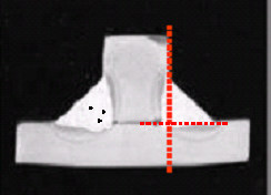
Weld Process Controls and Best Weld Practice Expertise would help analyze the root cause of this E71T-1 defect.

When weld shops select the traditional arc weld processes such as gas shielded flux cored and Pulsed MIG, there will be many process defects and issues beyond the welders control, why managers, engineers and supervisors will continue to suck on TUMs, and when internal weld NDT is required they will rarely get a good nights sleep. if you want to minimize (not eliminate) issues with gas shielded or pulsed MIG take a moment with my MIG and flux cored weld process control self teaching / training resources. However if you want to eliminate weld rework select a weld process that is capable and in 2020 there is only one weld process and that’s TIP TIG.
Like MIG, Gas Shielded Flux Cored is another Reverse Electrode Polarity process, and again this polarity contributes to distortion and the size of the weld’s HAZ.
Gas Shielded Flux Cored works with argon – 20 – 25% CO2, or if you want more weld fusion, (with more weld fumes) use straight CO2. (Kobelco is my wire of choice).
The flux composition of the Rutile EX0T-1 gas shielded wires. produces a rapid freeze thin slag that enables control of the 5G welds. However the slag also contributes extensively to the many common flux cored weld defects. The slag composition and thickness is not consistent and sometimes the slag freezes to quickly and the weld has insufficient slag protection resulting in weld porosity, trapped slag and extended inline porosity called Worm tracks.

The high all position deposition capability with the all position Flux Cored wires, again promote fast weld speeds with welds that lack insufficient weld energy for the weld mass produced. The slag often gets trapped resulting in slag inclusions. The wire flux composition – content is often inconsistent. The flux is also often contaminated with moisture during wire production or in wire storage and use. producing unexpected porosity and worm tracks. Pulsed MIG on All Position Code Quality Welds.
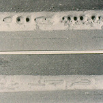
Left. E71T-1 Gas Shielded Flux Cored wire Vertical Up. Right. TIP TIG Vertical Up weld. Which weld do you think would pass X-Rays?

Someone who is interested in weld process optimization and weld controls would take a closer look at the above Flux Cored weld. Yes the weld reveals the welder had good skills and a steady hand and we all know that most weld shops believe that welder skills drive weld quality. However take a close look. Note the cold looking sluggish and the weld surface irregularity, the scalloped weld edges, the weld convexity, all are indications of insufficient weld fluidity from insufficient weld energy.
Welds like the above are often just given a surface inspection, however if internal weld NDT was applied to the welds on the heavy carbon steel parts, the first thing you would find is extensive Lack of Weld Fusion, and as I found after 35 years of examining small diameter gas shielded Flux Cored wires and welds, it would almost be impossible with these rapid freeze welds not to find Excessive Trapped Slag and Porosity. If I had made the above above Flux Cored welds, I would have used higher amp settings and given special consideration to the weld-ability and fluidity of the flux core wire selected.
What many weld shops don’t realize with gas shielded Flux Cored welds, is at the flux cored wire manufacturers, most of the popular gas shielded Flux Cored welds were developed in the 1980s – 90s and designed and tested with a CV MIG unit. If Multi-process or Inverter MIG power sources are used with these wires in the weld shop, in contrast to the regular CV MIG unit which has a flatter slope output, the more modern electronic weld power sources typically provide a steeper slope output, and therefore for a given Flux Cored wire feed rate with the CV units, the Invertors and Multi-process equipment will typically put out 15 to 25% less weld current. Please be aware that the above info is not attainable from your weld sales rep or equipment mfg. If you want this type of real world weld process / application info, you may wish to consider my Flux Cored, MIG, and TIP TIG self teaching / training programs below.
Remember with any arc weld, the best possible weld and welded part properties will come from a weld process that provides five prime functions;
- The arc plasma provides the highest weld energy.
- The weld is protected by an inert atmosphere.
- The polarity used is DCEN which enables a fast freeze weld making it easy to use for all positions.
- The deposition (weld speeds) and polarity enable the lowest part heat input. Four simple requirements for all code welds on any metals.
- The process with all position welds is easy to use.
TIP TIP ENABLES SIMILAR VERTICAL UP WELD SPEEDS TO PULSED MIG. TIP TIG typically delivers 200 to 400% higher weld deposition rates than DC TIG, producing similar all position weld travel rates as pulsed MIG. In contrast to traditional TIG, both the DCEN & Variable Polarity (alum) TIP TIG process continuously feeds the commonly used 0.035 – 0.045 (1 – 1.2 mm) diameter weld wires into the TIP TIG plasma sweet spot.
When TIP TIG is used on clean applications such as this Super Duplex fillet weld, note the untouched TIP TIG weld color which reveals lack of oxidation influence with the atmosphere. This is only possible with very low welded part heat input. With TIP TIG, weld shops should always anticipate the cleanest, defect free welds that produce the smallest weld HAZ, and this applies to most weld applications > 2 mm. Note try and replicate the fillet 1/4 weld shown on the left with either a duplex, stainless or inconel weld wire and the process of your choice.
TIP TIG is the only arc weld process that enables the highest arc weld energy with the lowest welded part heat input.
The DC TIP TIG process provides an arc temperature that can be twice as much as a MIG and FCAW arc. Keep in mind that with the TIP TIG unique weld wire to arc plasma placement enables with TIP TIG, improved TIG plasma coverage over the weld pool. Also the higher TIP TIG weld deposition rates enable higher TIG weld current to be further adding to the plasma energy. The TIP TIG process therefore simply enables more weld energy and improved weld fluidity than possible with DC TIG.
SO YOU WOULD LIKE TO SEE WHAT THE PERFECT WELD LOOKS LIKE WITH AN EASY TO USE WELD PROCESS THAT PROVIDES THE SAME EXTRAORDINARY WELD QUALITY IN ANY WELD POSITION.
In contrast to the Pulsed MIG weld if you want to view a weld that is optimum in 2020 and will still be optimum in 2050, a weld that provides much higher energy than is possible with any all position weld made with the Pulsed MIG mode or with an EX1T-1 weld wire, take a close look look at this TIP TIG video.
Carefully examine the TIP weld fluidity, the weld purity being produced, and thanks to the TIP TIG Electrode Negative polarity, the welds produced will always enable the lowest possible welded part heat for the best possible metallurgical results. No weld spatter. The lowest possible weld fumes and no concerns for weld fusion with those sluggish alloy welds. By the way its also the best weld process for any open root weld, and it requires less all position welder skills than either MIG or flux cored.
For seven decades, the manual regular DC/AC TIG, required the welder feed the weld wire. And due primarily to the TIG common arc length sensitivity and some other weld issues, for 70 plus years, regular TIG has been poorly suited as a “Manual Semi-automated” or Fully Automated arc weld process without fixed arc length or automated arc length adjustment equipment.
As weld shops are aware, the semi-automated MIG and gas shielded flux cored weld processes when used for flat and horizontal welds, not only enables on average, at least ten times greater weld deposition rate potential than regular DC TIG, but other important features of the semi-automated MIG and Flux Cored process, is the continuous feed of the MIG wire helps in the regulation of the manual weld speeds and helps deliver weld wire melt and weld solidification continuity.
In contrast to TIG, the MIG wire feeder dramatically reduces both the MIG and flux cored welder skill requirements. However the reality has been that for seven decades, in contrast to any MIG weld transfer mode or flux cored weld, the higher weld energy DC TIG process with its inert gas protection, has been the process to go to to when the highest manual arc weld quality was desired. To improve TIG it had to become a process capable of being a semi-automated weld process that delivers higher weld deposition rates.